In an old blog that I stopped maintaining several years ago, I had a few partial posts discussing multi-lead threads. To my surprise those posts still attract a large number of hits from Google. Since those posts really don't do a great job of explaining how to use multi-lead threads in pen making, I thought an updated post here would be beneficial to my readers.
Multi-lead or multi-start threads are commonly used in consumer products to decrease the number of turns required to screw on lids and caps. It would be very frustrating to require eight or nine turns of a jar lid to tighten it, or three or four turns of a pen cap to remove it.
My main use of multi-lead threads is on pens, so the example I will show is for a 4 lead thread that is based on an outside diameter of 0.492" on the pen barrel. I will also be talking about how to code this thread in Mach3 for turning on a CNC lathe. I have done it once or twice on a manual lathe and I'll talk briefly about how that works. Please understand I am not a master machinist. There are people out there who really do know what they are doing, and I expect that some of my practises would frustrate them. This is what works for me and many other pen makers that I know, and was developed primarily from experimentation.
A few things up front that I recommend you get if you are serious about experimenting with these types of techniques. First off you need a metal lathe. This may sound obvious but let me explain. Many pen makers are using wood lathes. Unfortunately these do not have the ability to thread using a fixed cutter. If you want to thread with them you are reduced to using taps and dies. That is ok for many applications, but really forces you to use standard sized threads. Custom taps and dies are available for multi-lead threads, but you are usually looking at hundreds of dollars to have them made. Being able to cut threads yourself on the lathe allows you to use odd diameters and thread pitches to accommodate what you want to design, instead of designing to a standard. A small metal lathe is fine as long as your work fits on it. Just remember that it is easy to make small parts on a large lathe, and usually very dangerous to make large parts on a small lathe. I usually recommend a 9x20 as a good size, and variable speed control will make your life much easier. There are plenty of resources out there with detailed reviews of the different 9x20 lathes on the market. Please learn how to use the threading feature of your lathe on standard threads before you try multi-lead threads.
Buy a copy of the Machinist's Handbook. Unless you need all of the latest and greatest CNC info in it, an older copy will do just fine. Yes a new copy will set you back $100+, but it is worth the money. I keep one in the shop and one in the office for quick reference when designing parts and coding. Unless you have great eyesight, avoid the small toolbox edition. Get a good set of digital calipers. The $30 set you bought is not giving you accurate measurements. A good pair of Mitutoyo calipers will be expensive, but as long as you don't drop them, they will provide you with accurate measurements for years. I've saved myself the cost of those calipers several times over in the past 3 years just by avoiding remaking parts that weren't measured properly.
Normal threads are expressed using a diameter-pitch notation. For instance 1/2-20 or 1-8. Lets take a look at the 1/2-20 thread first since it is the closest in diameter to the one we're discussing. The 1/2" diameter refers to the outside diameter of the male thread. It is also called the major diameter. The bottom of the thread is referred to as the minor diameter. For a 1/2-20 thread the minor diameter is 0.438". I'm not going to go into all of the details about theoretical and practical threads, but the minor diameter is the theoretical bottom if you used a sharp "V" cutter. The reality is that the bottom of a 1/2-20 has a diameter of 0.446" (you can read all about the math behind threads in the Machinist's Handbook.) That means that the thread is 0.027" deep at any point. With a pitch of 20 threads per inch, it will require 20 turns of a nut to move it 1". I usually thread 1/4" of the barrel. If we use this thread on the cap of a pen, it will take 5 turns of the cap to close the pen. That is just not acceptable.
To close the cap faster, we need a coarser thread. An 8 tpi thread is going to allow the cap to close in 2 turns. Unfortunately the smallest standard thread that uses a pitch of 8 tpi has a major diameter of 1". Not exactly ideal for the barrel of a pen. On top of that, an 8 tpi thread is more than twice as deep as a 20 tpi thread. Such a coarse thread doesn't look very attractive on a pen.
This is where a multi-lead thread comes in handy. We can combine 4 threads that each have a pitch of 8 tpi. When you look at the finished thread and use a thread gauge to determine the pitch, it will look like a 32 tpi thread. Because the combined pitch is 32 tpi, we'll use that to determine the minor diameter. I use a major diameter of 0.492", and minor diameter of 0.460". This is a little deeper than a 32 tpi thread should use, but I've found through experience that it works well for the plastics that are common in pen making.
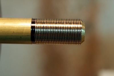
The first step in actually cutting this thread is to turn down the outside diameter to 0.492". In the example photographs below, I've turned down the first 1" of a brass rod. Next step is to turn a single thread that has a pitch of 8 tpi, to a depth of 0.460". The next bit is to figure out how to cut the second thread so that it is offset from the first by an appropriate amount. The easiest way is to start the next thread 1/4 of thread pitch farther way from the piece. In this case 0.031" (there is 0.125" between each peak of the thread, divided by the number of leads we have, gets us to 0.031".) Same thing for the next two leads. Keep moving the start point of the cutting cycle 0.031" farther back until you have cut all four threads.
Lets take a look at the g-code used to thread my pen barrels. All of these examples work with Mach3 Turn. If you are using a different control software, things may change slightly (although the dimension numbers should all be the same.) Here is the code that I used to turn the piece in the photos below:
01: G18 G40 G49 G90 G95 G80
02: M3
03: (TOOL# 6 THREAD 4 LEAD 8TPI THREAD FOR 0.950)
04: T0606
05: (SPINDLE 500RPM)
06: S500
07: #1 = 0.492 (START X)
08: #2 = 0.460 (FINISH X)
09: #3 = -0.950 (LENGTH TO THREAD)
10: G00 Z0.1
11: G00 X#1
12: M08
13: G76 X#2 Z#3 Q5 P0.125 J0.001 L45 H0.002 I29 C0.025
14: G00 z0.131 X#1
15: G76 X#2 Z#3 Q5 P0.125 J0.001 L45 H0.002 I29 C0.025
16: G00 Z0.162 X#1
17: G76 X#2 Z#3 Q5 P0.125 J0.001 L45 H0.002 I29 C0.025
18: G00 Z0.194 X#1
19: G76 X#2 Z#3 Q5 P0.125 J0.001 L45 H0.002 I29 C0.025
20: M09
21: G0 X2 Z2
22: M5
23: M30
If you drop this code into Mach3, please remove the line number: from each line or it won't work. Any line with ( ) is a comment and will be ignored by Mach3. It is very useful to comment your code so you can remember what you need to do 6 months down the road when you want to re-use it. Line 1-2 are the initialization strings that I use for my lathe. Those will probably change for yours. Line 4 is telling Mach3 to change to tool 6. That is my threading tool. Line 6 is setting the spindle speed. I'm using a speed of 500rpm because that is what I'm comfortable using for on my lathe and this material. You will need to experiment to find a good speed for your lathe. Start slow (no more than 100rpm,) and slowly work up to something more comfortable for you. Remember to take into account that your stepper motors must be able to accelerate fast enough to keep up with the spindle.
I am using variables in this code so that I can easily change the parameters that I modify from project to project. On lines 7-9 I set the start and finish diameters, as well as the Z co-ordinate to cut to. Line 10 is the start point of the cut for the first lead. I don't start it at Z0 because the steppers need a little distance to accelerate up to full speed. You may need to increase this number depending on your setup. Line 11 the cutter is moved to the starting diameter. Line 12 is where the threading cycle starts. M08 and M09 tell Mach3 where the threading cycle begins and ends.
On the G76 lines, the following variables have been used: X is the minor diameter, Z is the co-ordinate to cut to, Q is the number of spring passes, P is the pitch, J is the minimum depth of cut, L is the angle to taper the end of the cut, H is the depth of the first cut, I is infeed angle and C is the clearance in X. J and H in this example are very conservative numbers. Depending upon the material and machine, you will be able to take deeper cuts on each pass.
Line 14 is important. This is the line that sets up the second lead. For the first lead we started the cut at Z0.100. The second lead starts at Z0.131. Nothing else changes. That means it will cut the exact same thread, just offset by 90 degrees from the first one. Lines 16 and 18 do the same for the third and fourth leads. Really those three lines are where the magic of multi-lead threads happen. The last lines are just resetting the cutter and Mach3.
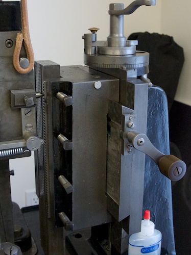
Things don't change much on a manual lathe. You'll be using a lead screw driven by the spindle, but otherwise the important details are the same. Setup your lathe to cut an 8 tpi thread. Set the compound slide to 0 degrees (it should move parallel to the Z axis.) Engage the lead screw and make sure the spindle speed is set to a low rpm. Advance the cutter so that it will take a light cut on the first pass. Start the lathe and keep your finger on the stop button. You need to be ready to stop the spindle when the cut is finished. Once you have stopped it, do not disengage the lead screw. Instead back the cutter out so that it is clear of the piece. Put the lathe in reverse until you are past the starting point of the cut. Put the lathe in forward, advance the cutter to take a cut a couple of thou deeper than the last one. Start the lathe and repeat the procedure from the first cut.
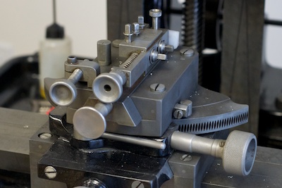
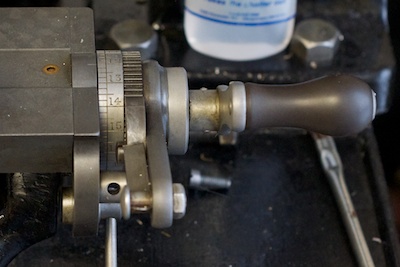
Once you have cut the first lead, reverse the carriage to the start of the cut. Now you need to move the start point of the cut by 0.031". Use the compound slide to move the cutter away from the piece by that amount. Repeat the same cut, stop, reverse pattern of the first lead. You will now have a second lead cut. Repeat the same 0.031" movement of the compound slide for the third and fourth leads.
Regardless of if you are using a manual or CNC lathe, please experiment using conservative speeds and depths of cut on a free machining material first. Once you can reproduce the same part a couple of times in a row, then move on to different materials.
And the final thing I will talk about is the matching nut, or in my case cap. To make a cap matching the above thread, bore the piece to 0.470" ID, and thread from 0.470" to 0.515" (if you are using the g-code from above, variable #1 should be 0.470 and #2 should be 0515.)
I hope that all of this rambling has made some sense to someone other than me. If you have questions, feel free to send me an email. I can't guarantee that I can answer them, but I would be happy to try.
(Note about the photos below. Sharp eyed readers will notice that the sequence of the cuts is wrong. The third photo shows the second lead being cut, except that it is really the third lead. When I was stopping the machine after the first lead was cut to photograph the piece, it decided to skip the second lead and move onto the third lead instead. It then cut the fourth lead fine, and I went back and cut the second lead last. If you follow the instructions above, you will cut them in the correct order, and your piece will look the same as the last photo.)


